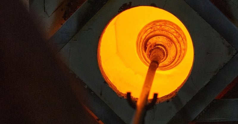
An optical fibre starts as a thick glass cylinder called a preform. By the end of production, that cylinder has been drawn into a strand about as thin as a human hair.
Glass processing equipment across the line includes chemical delivery systems. Deposition lathes, draw towers, coating units, and even inspection instruments are included. A problem at one stage can affect the finished fiber.
Building the glass preform
Its center forms the light-carrying core. The surrounding glass becomes the cladding. Several methods are used to manufacture preforms. Modified chemical vapour deposition, commonly shortened to MCVD, forms glass layers inside a rotating silica tube. Outside vapor deposition builds material on the exterior of a starting rod. Vapour axial deposition grows the preform along its length.
Each method requires control over chemical flow, temperature, and movement. Gas delivery panels meter the compounds that form the glass. Dopants may also be introduced to change the refractive index of a particular layer.
In an MCVD system, the silica tube rotates in a glass-working lathe. A burner travels along its length. This leaves thin glass layers on the inner wall. Lathe alignment matters here.
Turning porous material into clear glass
Some deposition processes produce a soft, porous mass known as a soot body. It does not yet have the clear appearance of optical glass. It must first enter a consolidation furnace. The soft soot body then changes—it becomes dense, clear glass.
Conditions must be controlled throughout this stage. The gas mixture helps keep contaminants away. Heat must spread evenly through the soot body. Cold areas may not become fully solid. Excess heat may change the preform’s shape.
Measuring systems check their diametre and roundness. They also examine its internal structure. Another instrument—the refractive index analyser—checks the deposited layers. This confirms whether they match the required optical design.
Drawing a fine, consistent strand
The completed preform moves to a draw tower, one of the most recognisable pieces of glass processing equipment in a fibre plant. The finished preform now moves to the draw tower. This is where the thick glass rod becomes a very fine strand.
Standard telecommunications fibre usually has a glass diameter of about 125 micrometers—roughly the thickness of a human hair. A laser gauge measures that diameter. It does not touch the hot, fragile strand. Readings are sent back to the production controls. This can change the drawing speed or furnace conditions if the fibre begins to move outside its target range.
Tension also needs attention. Load sensors and motor controls keep the draw smooth as the preform becomes smaller.
Applying the protective coating
Freshly drawn glass is vulnerable to tiny surface flaws. Thus, the coating is applied on the draw tower before routine handling begins.
The fibre travels through a coating applicator containing liquid polymer. Many products receive two layers. Pressure controls manage the flow of the liquid coating. Gauges then check its thickness. The first coating layer is usually soft. It acts like a cushion around the glass. The second layer is harder and protects the fiber during later handling.
Both layers must remain centred on the glass. An uneven coating can create weak areas. The applicator must stay clean during production.
UV lamps harden the coating right away. The lamp strength and line speed must be carefully balanced. Too little UV energy leaves the coating soft or sticky. Poor curing can also make the coating less effective. Some production lines use several UV chambers to complete the cure in stages.
Finding defects before cabling
Optical sensors look for changes in diametre and coating faults. Check surface damage and other irregularities also. The advantage of online inspection is speed. Operators can respond to a developing problem before an entire production run is affected.
Finished fibre also goes through proof testing. During this step, controlled tension is applied. Doing this can reveal weak sections that could fail during cabling or installation. Optical tests measure attenuation. This shows how much signal strength is lost as light travels through the fibre. Geometry instruments check core position. They also look at cladding shape and concentricity.
No single machine determines fibre quality. The result comes from the full line, from chemical delivery through final testing. Each stage depends on accurate equipment and consistent measurements.